

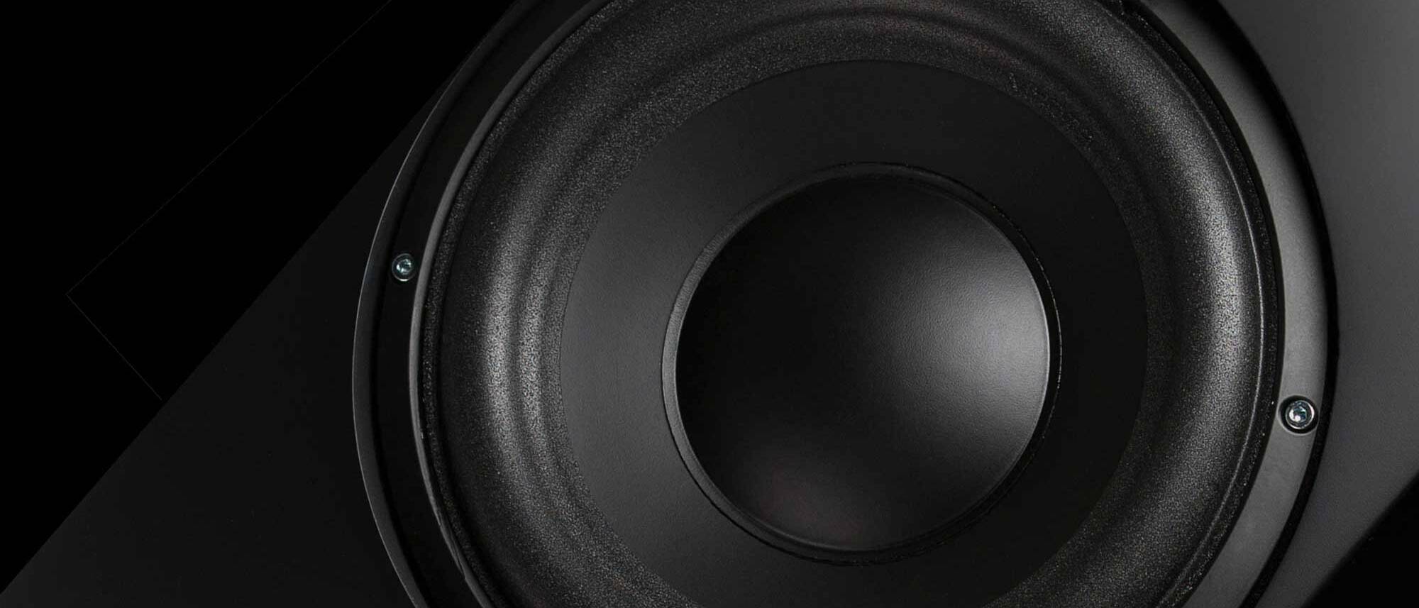


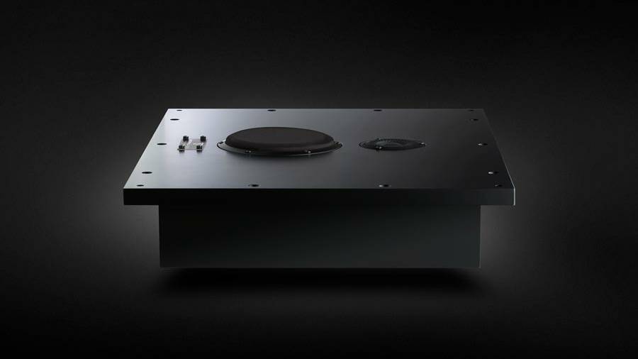
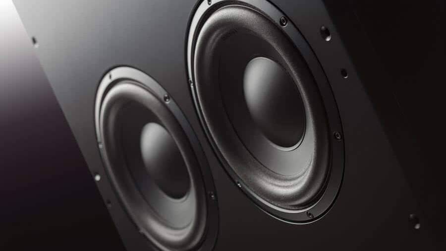


The membrane, the suspensions
ATOHM "ABSOLUTE SERIES" MEDIUM BASS / MEDIUM DRIVERS
Numerous investigations have led Atohm, our R&D partner led by Thierry COMTE, to understand that the material properties of the membrane certainly influence the frequency response but that the overall result is very significantly conditioned by the rigidity and length of the coil support, the mass of the winding, the nature and quantity of glue used for the support/membrane junction as well as the geometry, mass and viscoelastic properties of the peripheral suspension. The movement of the diaphragm as a perfect “piston” exists only for a limited frequency band. The directivity of a perfect piston is always proportional to the dimensions of its emissive surface (not to its rigidity).
The various splitting modes of the cone and also of the suspension increase or decrease the sound pressure according to their amplitudes and phases. Above certain frequencies, the coil support ceases to transmit movement and deforms under the joint action of the cone and the mass of the winding. This buckling also helps to reinforce or cancel out the overall movement of the cone (in a way the support acts like a “spring”). All the moving parts form an inseparable “whole”. As such, it is advisable to optimise this “whole” according to the objectives to be achieved, not forgetting the imperatives of reliability and reproducibility to be guaranteed.

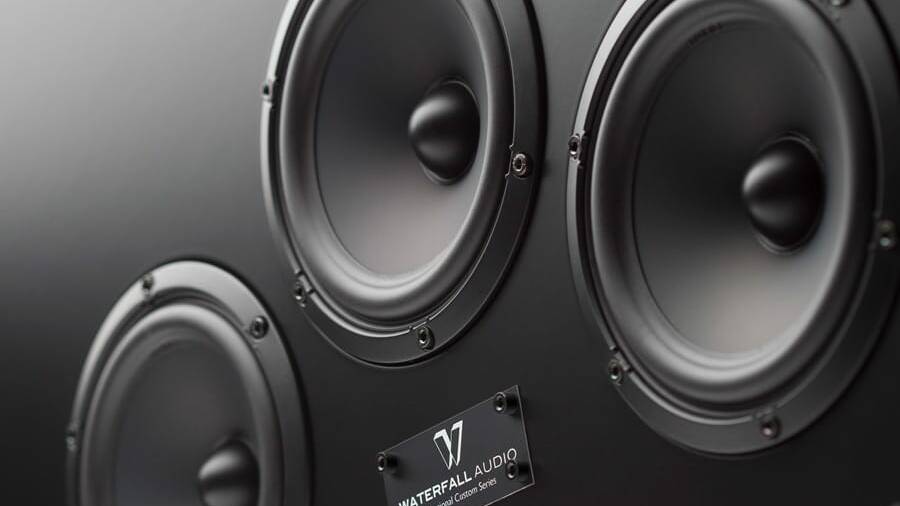
The aim of the developments is to obtain bass-midrange drivers with a frequency response very close to the theoretical ideal in a band between 30 Hz and 4000 Hz. The drivers are equipped with a special alloy diaphragm in order to push the audible fractions beyond this useful band. For the same purpose, the diaphragm is combined with a kapton/nomex coil support so that the movement is perfectly transmitted in this nominal frequency band. Beyond this range, the support and the associated adhesive joint limit the transmission and absorb some of the energy. The loudspeakers are also provided with a peripheral suspension with a particular profile favouring a progressive splitting (LDS™ Technology) without marked accident in the useful band (typically between 700 Hz and 1800 Hz).
Extensive simulations (finite element method) and laser interferometry measurements, have led to the optimisation of the interactions between the different materials and the development of innovative geometries of the speaker’s constituent parts. The frequency response of the loudspeakers is characterised by exceptional linearity over the useful band. Beyond that, the response is corrected by the use of an adapted filter cell. Thanks to the use of rigid materials and perfectly stable adhesives, the performance is fully reproducible from one unit to another with a high level of precision (which is not the case with a paper or Kevlar® membrane for example).
Absolute Series
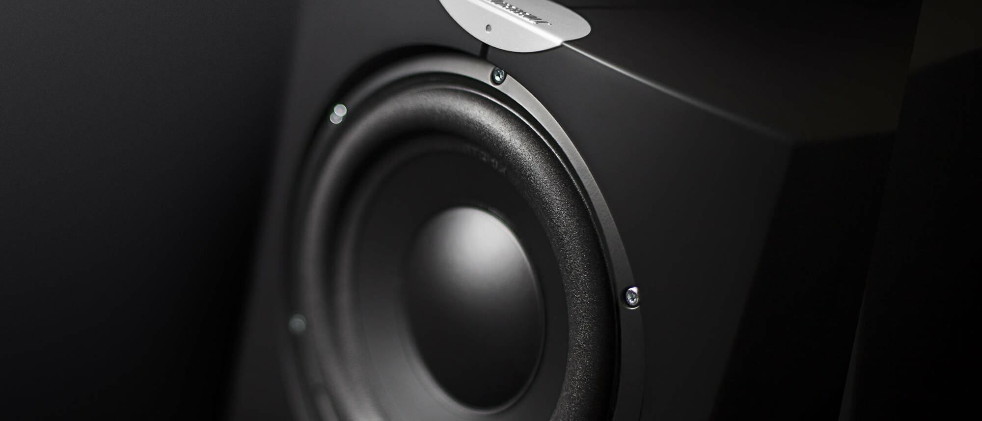
THE SUSPENSION-SPIDER PAIR
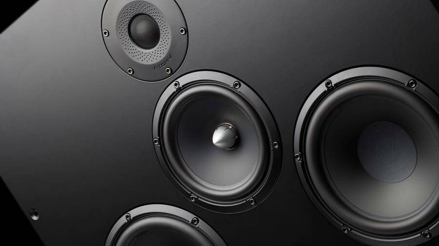
The diaphragm of the loudspeaker is held by its suspensions (peripheral suspension and spider). These suspensions constitute a return spring. In absolute terms, the stiffness coefficient of this assembly should be perfectly constant and symmetrical ( F= k.X ). In practice, however, it is neither constant nor symmetrical. The return force generated is therefore no longer directly proportional to the required displacement. In a way, this prevents the diaphragm from being placed precisely in the theoretical position that the moving coil is trying to force it into.
The result of extensive research and experimentation, the peripheral suspensions and spiders of the ‘Absolute Series’ loudspeakers have been optimised to achieve a substantially constant and perfectly symmetrical stiffness coefficient. Their respective geometry and mechanical summation allow for large excursion capacities. Moreover, provided with a specific profile (LDS™ technology), the suspension progressively splits at midrange frequencies (between 700 and 1800 Hz). Finally, the constituent materials have been selected to guarantee great reliability as well as perfect stability over time.

Force Without Inductance
The Motor: FWI® Technology
The driving force applied to the diaphragm (BL) is the result of the electric current flowing in the coil and the magnetic flux produced by the magnet in the air gap. In absolute terms, this flux should be constant whatever the position of the coil. In practice, however, it is highly dependent on the geometry of the pole pieces on the one hand and is modulated by the alternating components generated by the moving coil on the other.
Indeed, under the action of the current, the coil generates its own magnetic field. It is not the latter that is used to create the driving force. This alternating magnetic field acts as a parasite and significantly disturbs the continuous flow of the magnet. Alternatively, it increases or decreases the value of the DC flux in the air gap. Moreover, this disturbance is proportional to the electric current flowing in the coil.

Optimised by the finite element method, the FWI™ technology motor has been designed to achieve a large force factor, perfectly symmetrical over a very wide range of excursion. The motors feature powerful ferrites and pole pieces designed to conduct maximum magnetic flux. The flux density reaches 11000 gauss in the air gap of an LD150 (6mm height) and 11600 gauss in the air gap of an LD180 (6mm height). The parasitic interactions of the moving coil were taken into account in order to obtain a very low and constant inductance value whatever its position. The core and the copper ring that covers it have an innovative geometry. Their proportions and dimensions have been the subject of numerous investigations (simulations and prototypes) in order to satisfy these electromagnetic criteria, but also to allow optimum evacuation of the heat generated by the moving coil and to ensure the correct decompression of the motor.
ANALYSIS OF THE GRAPH
Force Factor
The blue curve represents the measurement of a competitor loudspeaker of similar size. We can see a significant asymmetry in this factor. It remains relatively constant when the voice coil leaves the motor, but drops very quickly when the voice coil enters the air gap. The movement of the diaphragm is strongly degraded on negative alternations. During large coil excursions the behaviour becomes unstable. The winding tends to “leak” from the midpoint and oscillate at the bottom of the motor (where the value of B/L is lowest) instead of oscillating freely around the 0 point.
The excursion and dynamic capabilities of this unit are largely limited. Distortion appears even at small excursions. The red curve represents the LD150 measurement. This curve shows a much wider plateau and perfect symmetry. The excursion capacities are large and the coil always oscillates around the reference point (no instability). The distortion per harmonic remains very low over a wide excursion range.

Electrical Inductance
Winding inductance value
The blue curve represents the measurement of the same loudspeaker as in the previous measurement. We can see a large variation and a total asymmetry of the inductance value. The inductance is high when the coil goes into the motor and low when it comes out. Depending on the amplitude of the current flowing through it, the coil is irreversibly “attracted” to the bottom of the motor (where the inductance value is highest) instead of oscillating freely around the 0 point. This phenomenon results in the creation of rank 3 harmonic distortion. Furthermore, this variation in inductance leads to a significant fluctuation in dynamic impedance (a fluctuation of about 2 ohms at 1000 hz when this 4 ohms speaker is loaded to +/-4mm at low frequencies).
This results in a high level of intermodulation distortion to which can be added “current” distortion if the amplifier is not designed to cope with such fluctuations. The red curve represents the LD150 measurement and shows the near-linearity of the voice coil inductance (and therefore perfect symmetry). The coil is therefore not “attracted” to the bottom of the motor and oscillates freely around the 0 point. The rate of distortion per third harmonic is reduced to a great extent. In addition, the dynamic impedance of this unit remains perfectly stable as the variation is practically zero. The intermodulation distortion is therefore very low and the amplifier works under much better conditions.

SOCIAL MEDIA
KEEP IN TOUCH
Follow us on all our social networks and receive the latest news on Facebook, Twitter and Linkedin, how-to videos on Youtube and beautiful inspiring photos on Instagram and Pinterest.